Verification
The verification environment (testbenches, testcases, etc.) for the CV32E40P core can be found at core-v-verif. It is recommended to start by reviewing the CORE-V Verification Strategy.
v1.0.0 verification
In early 2021 the CV32E40P achieved Functional RTL Freeze (released with cv32e40p_v1.0.0 version), meaning that is has been fully verified as per its Verification Plan. Final functional, code and test coverage reports can be found here.
The unofficial start date for the CV32E40P verification effort is 2020-02-27, which is the date the core-v-verif environment “went live”. Between then and RTL Freeze, a total of 47 RTL issues and 38 User Manual issues were identified and resolved [1].
A breakdown of the RTL issues is as follows:
“Found By” |
Count |
Note |
|---|---|---|
Simulation |
18 |
See classification below |
Inspection |
13 |
Human review of the RTL |
Formal Verification |
13 |
This includes both Designer and Verifier use of FV |
Lint |
2 |
|
Unknown |
1 |
A classification of the simulation issues by method used to identify them is informative:
Simulation Method |
Count |
Note |
|---|---|---|
Directed, self-checking test |
10 |
Many test supplied by Design team and a couple from the Open Source Community at large |
Step & Compare |
6 |
Issues directly attributed to S&C against ISS |
Constrained-Random |
2 |
Test generated by corev-dv (extension of riscv-dv) |
A classification of the issues themselves:
Issue Type |
Count |
Note |
|---|---|---|
RTL Functional |
40 |
A bug! |
RTL coding style |
4 |
Linter issues, removing TODOs, removing `ifdefs, etc. |
Non-RTL functional |
1 |
Issue related to behavioral tracer (not part of the core) |
Unreproducible |
1 |
|
Invalid |
1 |
Additional details are available as part of the CV32E40P v1.0.0 Report.
v2.0.0 verification
The table below lists the 7 configurations with cv32e40p_top parameters values verified in the scope of CV32E40Pv2 project using both Formal-based and Simulation-based methodologies.
Verified Configurations (CFG_”config name”) |
|||||||
|---|---|---|---|---|---|---|---|
Top Parameters |
P |
P_F0 |
P_F1 |
P_F2 |
P_Z0 |
P_Z1 |
P_Z2 |
COREV_PULP |
1 |
1 |
1 |
1 |
1 |
1 |
1 |
COREV_CLUSTER |
0 |
0 |
0 |
0 |
0 |
0 |
0 |
FPU |
0 |
1 |
1 |
1 |
1 |
1 |
1 |
ZFINX |
0 |
0 |
0 |
0 |
1 |
1 |
1 |
FPU_ADDMUL_LAT |
0 |
0 |
1 |
2 |
0 |
1 |
2 |
FPU_OTHERS_LAT |
0 |
0 |
1 |
2 |
0 |
1 |
2 |
Verification environment is described in CORE-V Verification Strategy and used the so-called Step-and-Compare 2.0 methodology. It is using an Imperas® model connected in the test-bench through an RVVI interface as shown by following figure:
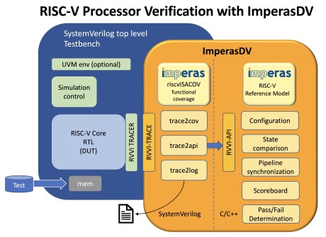
Figure 2 ImperasDV framework
CV32E40Pv2 achieved RTL Freeze (released with cv32e40p_v2.0.0 version) mid-April 2024, meaning that is has been fully verified as per its Verification Plan. Final functional, code and test coverage reports can be found here: CV32E40P v2.0.0 Report.
It is to be mentioned that CV32E40Pv2 has successfully executed RISCOF (RISC-V COmpatibility Framework) for RV32IMCF extensions. Report can be found here.
Formal verification
To accelerate the verification of more than 300 XPULP instructions, Formal Verification methodology has been used with Siemens EDA Onespin tool and its RISC-V ISA Processor Verification app.
The XPULP instructions pseudo-code description using Sail language have been added to the RISC-V ISA app to successfully formally verify all the CV32E40P instructions, including the previously verified standard IMC together with the new F, Zfinx and XPULP extensions and all additional custom CSRs.
Example:
{
  "name": "CV.SDOTUP.B",
  "disassembly": "cv.sdotup.b {rd},{rs1},{rs2}",
  "decoding": "1001100 rs2 rs1 001 rd/rs3 1111011",
  "restrictions": "",
  "execution": "X(rd) = X(rs3) + EXTZ(mul(X(rs1)[7..0],X(rs2)[7..0])) +
                                 EXTZ(mul(X(rs1)[15..8],X(rs2)[15..8])) +
                                 EXTZ(mul(X(rs1)[23..16],X(rs2)[23..16])) +
                                 EXTZ(mul(X(rs1)[31..24],X(rs2)[31..24]))"
},
Those SAIL instructions description are then used to automatically generate more than 430 assertions and 29 CSRs descriptions. Those assertions have been applied on the 7 different configurations listed in Verified configurations table.
RTL code coverage is generated using Siemens EDA Onespin Quantify tool which uses RTL mutation to check assertions quality and can produce standard UCDB database that can be merged with simulation one afterwards.
Simulation verification
core-v-verif verification environment for v1.0.0 was using a step&compare methodology with an instruction set simulator (ISS) from Imperas Software as the reference model. This strategy was successful, but inefficient because the step&compare logic in the testbench must compensate for the cycle-time effects of events that are asynchronous to the instruction stream such as interrupts, debug resets plus bus errors and random delays on instruction fetch and load/store memory buses. For verification of v2.0.0 release of the CV32E40P core, the step-and-compare and the ISS have been replaced by a true reference model (RM) called ImperasDV. In addition, the Imperas Reference Model has been extended to support the v2 XPULP instructions specification.
Another innovation for v2.0.0 was the adoption of a standardized tracer interface to the DUT and RM, based on the open-source RISC-V Verification Interface (RVVI). The use of well documented, standardized interfaces greatly simplifies the integration of the DUT with the RM.
Results summary
30 issues were identified by Formal Verification and 10 by Simulation methodologies, all have been resolved.
Here is the breakdown of all the issues:
“Found By” |
Count |
Note |
|---|---|---|
Formal Verification |
30 |
All related to features enabled by |
Simulation |
10 |
|
Lint |
2 |
A classification of the Formal Verification issues by type and their description are listed in the following tables:
Type |
Count |
Note |
|---|---|---|
User Manual |
12 |
Instructions description leading to mis-interpretation |
RTL bugs |
18 |
See classification below |
Issue Type |
Count |
Note |
|---|---|---|
Illegal instructions exception |
5 |
F and XPULP instructions corner cases or CSR accesses not flagged as Illegal instructions exception. |
Multi-cycle F instructions |
8 |
FDIV, FSQRT or respective F instructions (when FPU_ADDMUL_LAT or FPU_OTHERS_LAT = 2) are executed in the background and the pipeline can continue to execute other instructions as long as there is no Read-After-Write or Write-After-Write dependency. When the multi-cycle F instructions are finally writing back their result in the Register File, this register update can corrupt on-going instructions behaviour or result. This is the case for Misaligned Loads, Post-Incremented Load/Stores, MULH, JALR or cv.add*NR/cv.sub*NR. |
F instructions result or flags |
5 |
F result or flags computations is incorrect with respect to IEEE 754-2008 standard. |
A classification of the Simulation issues by type and their description are listed in the following tables:
Type |
Count |
Note |
|---|---|---|
RTL bugs |
10 |
See classification below |
Issue Type |
Count |
Note |
|---|---|---|
Multi-cycle F instructions |
5 |
Data forward violation between XPULP instructions and muticycle F instructions. |
Hardware Loops |
3 |
Incorrect behavior when count programmed with 0 value. lpendX CSR updated by a cancelled instruction. lpcountX not updated after a pipeline flush due to a CSR access. |
Deadlock |
1 |
Bug resolution for multicycle F instructions created a deadlock when conflicting Register File write between ALU and FPU. |
MSTATUS.FS incorrect value |
1 |
FS was not updated following any Floating Point Load instruction. |
Tracer
The module cv32e40p_rvfi_trace can be used to create a log of the executed instructions.
It is a behavioral, non-synthesizable, module instantiated in the example testbench that is provided for
the cv32e40p_top. It can be enabled during simulation by defining CV32E40P_RVFI_TRACE_EXECUTION.
Output file
All traced instructions are written to a log file.
The log file is named trace_core.log.
Trace output format
The trace output is in tab-separated columns.
Time: The current simulation time.
Cycle: The number of cycles since the last reset.
PC: The program counter
Instr: The executed instruction (base 16). 32 bit wide instructions (8 hex digits) are uncompressed instructions, 16 bit wide instructions (4 hex digits) are compressed instructions.
Decoded instruction: The decoded (disassembled) instruction in a format equal to what objdump produces when calling it like
objdump -Mnumeric -Mno-aliases -D. - Unsigned numbers are given in hex (prefixed with0x), signed numbers are given as decimal numbers. - Numeric register names are used (e.g.x1). - Symbolic CSR names are used. - Jump/branch targets are given as absolute address if possible (PC + immediate).Register and memory contents: For all accessed registers, the value before and after the instruction execution is given. Writes to registers are indicated as
registername=value, reads asregistername:value. For memory accesses, the physical address (PA) of the loaded or stored data is reported as well.
Time Cycle PC       Instr    Decoded instruction Register and memory contents
 130    61 00000150 4481     c.li    x9,0        x9=0x00000000
 132    62 00000152 00008437 lui     x8,0x8      x8=0x00008000
 134    63 00000156 fff40413 addi    x8,x8,-1    x8=0x00007fff  x8:0x00008000
 136    64 0000015a 8c65     c.and   x8,x9       x8=0x00000000  x8:0x00007fff  x9:0x00000000
 142    67 0000015c c622     c.swsp  x8,12(x2)   x2:0x00002000  x8:0x00000000 PA:0x0000200c