CV32E4* Simulation Testbench and Environment
As stated in the PULP-Platform Simulation Verification chapter (in the Executive Summary), CV32E40P verification followed a two-pronged approach using an updated RI5CY testbench, hereafter referred to as the core testbench in parallel with the development of a UVM environment. The UVM environment was developed in a step-wise fashion adding ever more capabilities.
The UVM environment uses the Google random-instruction generator for stimulus creation, the Imperas Instruction Set Simulator (ISS) for results prediction. It is also capable running hand-coded code-segments (test-programs) such as those developed by the RISC-V Compliance Task Group.
The end-goal is to have a single UVM-based verification environment capable of “industrial grade” verification of the CORE-V family of cores, startng with the CV32E40P and the CV32E4* cores. This environment is always evolving to meet the needs of curent and future cores.
Core Testbench
The “core” testbench, is essentially the RI5CY testbench (shown in Illustration 1 of PULP-Platform Simulation Verification) with some slight modifications. It is named after the directory is it located in. This testbench has the ability to run the directed, self-checking RISC-V Compliance and XPULP test programs (mostly written in Assembler) used by RISC-V and will be used to update the RISC-V Compliance and add XPULP Compliance testing for the CV32E40P. These tests are the foundation of the Base Instruction Set and XPULP Instruction Extensions captured in the CV32E40P verification plan.
The testbench has been modified in the following ways:
Fix several Lint errors (Metrics dsim strictly enforces the IEEE-1800 type-checking rules).
Update parameters as appropriate.
Some RTL files were placed in the core directory – these have been moved out.
Support UVM error messages.
(TBD) Updates to the end-of-simulation flags in the Virtual Peripherals.
The CV32E40* UVM Verification Environment
This sub-section discusses the structure and development of the UVM verification environment under development for CV32E40*. This environment is intended to be able to verify the CV32E40P and CV32E40 devices with only minimal modification to the environment itself.
First Generation UVM Environment
The first generation environment has been supplanted by subsequent generations to the point where is it no long useful to discuss it.
Second Generation UVM Environment
The second generation environment is shown in Illustration 2. Phase 2 introduces the Google Random Instruction Generator and the Imperas ISS as a stand-alone components. The most significant capabilities of the second generation environment are:
Ability to use SystemVerilog class constraints to automatically generate testcases.
Results checking is built into the environment, so that testcases do not need to determine and check their own pass/fail criteria.
Simple UVM Agents for both the Interrupt and Debug interfaces. ToDo: show this in the Illustration.
Ability to run any/all testcases developed for the Phase 1 environment.
Support either of the CV32E40P or CV32E40 with only minor modifications.
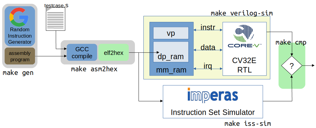
Illustration 2: Second Generation Verification Environment for CV32E
As shown in Illustration 2, the environment is not a single entity. Rather, it is a collection of disjoint components, held together by script-ware to make it appear as a single environment. When the user invokes a command to run a testcase, for example, make xrun-firmware [10], a set of scripts and/or Makefile rules are invoked to compile the environment and test(s), run the simulation(s) and check results. The illustration shows the most significant of these:
make gen: this is an optional step for those tests that run stimulus generated by the Google random instruction generator. Tests that use manually generated or externally sourced tests will skip this test. The generator produces an assembly-language file which is used as input to asm2hex.
make asm2hex: this step invokes the SDK (riscv-gcc tool-chain) to compile/assemble/link the input program into an ELF file. The input program is either from the make gen step or a previously written assembler program. The ELF is translated to a hexfile, in verilog “memh” format, that can be loaded into a SystemVerilog memory.
make sv-sim: this step runs a SystemVerilog simulator that compiles the CV32E and its associated testbench. As with the RI5CY testbench, the asm2hex generated hexfile is loaded into Instruction memory and the core starts to execute the code it finds there. Results are written to an actual results output file.
make iss-sim: this step compiles and runs the Instruction Set Simulator, using the same ELF produced in the make asm2hex step. The ISS thereby runs the same program as the RTL model of the core and produces an expected result output file.
make cmp: here a simple compare script is run that matches the actual results produced by the RTL with the expected results produced by the ISS. Any mismatch results in a testcase failure.
Phase 2 Environment Reference Model (ISS) Integration
Illustration 2 shows the ISS as an entity external to the environment. Phase 3 adds significant capabilies to the environment, notably the integration of the ISS as a fully integrated component in the UVM environment and a Step-and-Compare instruction scoreboard. After Phase 3 the Imperas ISS is used as the reference model to predict the status of the core’s PC, GPRs and CSRs after each instruction is executed. (Note that after this point in the document the terms “RM” and “ISS” are often used interchangeably.)
Wrapping the RM in a DPI layer allows the RM to be integrated into the UVM environment and thus controllable via the UVM run-flow. The benefit of this is that testcases will have direct control over the operation of the RM and comparision between the predictions made by the RM and actual instruction execution by the Core are done in real time. This is a significant aid to debugging failures.
Step-and-Compare
The integrated RM is used in a step-and-compare mode in which the RM and RTL execution are in lock-step. Step and compare is invaluable for debug because the RM and RTL are executing the same instruction in a compare cycle.
The table below contains the main signals used in stepping and comparing the RTL and RM.
Name |
Type |
Meaning |
|---|---|---|
step_compare_if.ovp_cpu_retire |
event |
RM has retired an instruction, triggers ev_ovp event |
step_compare_if.riscv_retire |
event |
RTL has retired an instruction, triggers ev_rtl event |
step_ovp |
bit |
If 1, step RM until ovp.cpu.Retire event |
ret_ovp |
bit |
RM has retired an instruction, wait for compare event. Set to 1 on ovp.cpu.Retire event |
ret_rtl |
bit |
RTL has retired an instruction, wait for compare event. Set to 1 on riscv_tracer_i.retire event |
ev_ovp |
event |
RM has retired an instruction |
ev_rtl |
event |
RTL has retired an instruction |
ev_compare |
event |
RTL and RM have both retired an instruction. Do compare. |
Referring to Illustration 3:
The simulation starts with step_rtl=1. The RTL throttles the RM.
Once the RTL retires an instruction, indicated by ev_rtl, the RM is commanded to Step and retire an instruction, indicated by ev_ovp.
The testbench compares the GPR, CSR, and PC after both the RTL and RM have retired an instruction.
Once the testbench performs the compare, step_rtl asserts, event ev_compare is triggered, and the process repeats.
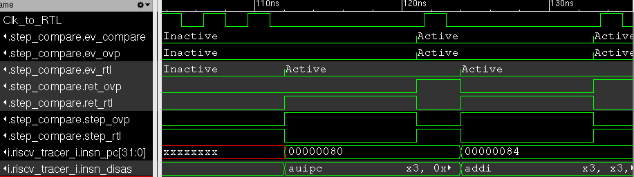
Illustration 3: Step and Compare Sequencing
Step and compare is accomplished by the uvmt_cv32_step_compare module.
Compare
RTL module riscv_tracer flags that the RTL has retired an instruction by triggering the retire event. The PC, GPRs, and CSRs are compared when the compare function is called. The comparison count is printed at the end of the test. The test will call UVM_ERROR if the PC, GPR, or CSR is never compared, i.e. the comparison count is 0.
GPR Comparison
When the RTL retire event is triggered <gpr>_q may not yet have updated. For this reason RTL module riscv_tracer maintains queue reg_t insn_regs_write which contains the address and value of any GPR which will be updated. It is assumed and checked that this queue is never greater than 1 which implies that only 0 or 1 GPR registers change as a result of a retired instruction.
Illustration 4 demonstrates that for a lw x11, -730(x11) instruction the GPR value is updated one clock cycle after the RTL retire signal. The load to x11 is retired but RTL value riscy_GPR[11] has not updated to 0x075BCD15 yet. However, the queue insn_regs_write has been updated and is used for the compare. It is assumed that all other RTL GPR registers are static for this instruction and can be compared directly.
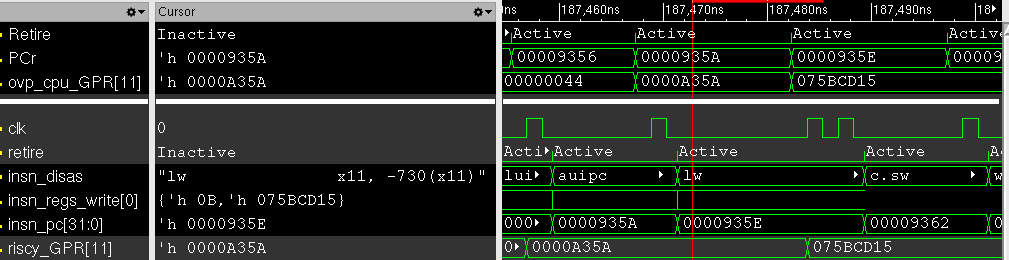
Illustration 4: Purpose of queue insn_regs_write
If the size of queue insn_regs_write is 1 the GPR at the specified address is compared to that predicted by the RM. The remaining 31 registers are then compared. For these 31 registers, <gpr>_q will not update due to the current retired instruction so <gpr>_q is used instead of insn_regs_write.
If the size of queue insn_regs_write is 0 all 32 registers are compared, <gpr>_q is used for the observed value.
CSR Comparison
When the RTL retire event is triggered the RTL CSRs will have updated and can be probed directly. At each Step the RM will write the updated CSR registers to array CSR which is an array of 32-bits indexed by a string. The index is the name of the CSR, for example, mstatus. Array CSR is fully traversed every call of function compare and compared with the relevant RTL CSR. A CSR that is not to be compared can be ignored by setting bit ignore=1. An example is time, which the RM writes to array CSR but is not present in the RTL CSRs.
Step-and-Compare 2.0
The second generation of step-and-compare builds upon and fixes many issues with the previous iteration of step-and-compare while maintaining the same verification effectiveness.
Formalize interface definition for the processor under test
Formalize interface definition for the ISS/Reference Model
Implement the Step-and-Compare architecture in UVM using standard methodologies such as UVCs (Universal Verification Components) when applicable.
Encapsulate data collection and movement throughout the testbench as transactions
Provide standard logging mechansims for Step-And-Compare to facilitate easy debug and triage
RVFI
The monitoring of processor activity was enabled by the tracer in the cv32e40p. The tracer was a SystemVerilog bound to the cv32e40p RTL that monitored all processor activities such as GPR, PC and CSR state. However the tracer interface was difficult to maintain and implemented an unspecified interface, requiring customized frequent changes in the Step-and-Compare implementation.
For future Step-and-Compare implementations, the RISC-V Formal Interface (RVFI) will be adapted to implement the processor monitor for the solution. In general the RVFI will follow its standard but may be adapted for extra requirements introduced by its usage in Step-and-Compare. All attempts will be made to ensure backwards-compabitibility to the initial RVFI specification.
‘The existing RVFI specification can be found here: <https://github.com/SymbioticEDA/riscv-formal/blob/master/docs/rvfi.md>’_ Any extensions to the RVFI will be described in this Verification Strategy document.
The RVFI consists of 2 major components. First, the processor itself must implement an RVFI SystemVerilog module that can be bound (using SystemVerilog bind) or another unobtrusive integration into the processor itself. The RVFI module presents a wired interface of the following signals. Note that the entire signal set may be replicated if the processor support retiring multiple instructions on the same clock cycle.
Note
The table below indicates RVFI signals which are not currently explicitly used in the RVFI/RVVI. However note that all RVFI signals are monitored and collected into sequence items for usage in logging and analysis port subscribers.
Signal |
Description |
|---|---|
rvfi_valid |
Signals that the rest of the bus is valid |
rvfi_order |
Monotonically increasing value which represents instruction ordering. Can be used with multiple retirment instruction interfaces to re-order instructions (if needed) |
rvfi_insn |
The instruction word that was retired. This should represent the ISA instruction directly. For example if this is a C instruction it should be the 16-bit instruction word and not the uncompressed ILEN-bit word. |
rvfi_intr |
Indicates that the current instruction is the first of a trap handler. This could map an interrupt, exception, or debug handler |
rvfi_trap |
Indicates that an instruction will cause an exception such as a misaligned read or write (if not supported), a jump to a misaligned address (if not supported) or an illegal instruction. |
rvfi_halt |
Indicates that an instruction is last before instruction execution halt. an interrupt, exception, or debug handler. Not currently used in RVFI/RVVI checkers |
rvfi_dbg |
Indicates that an instruction is the first instruciton of a debug handler. |
rvfi_mode |
Indicates the processor mode for this instruction (0-U, 1-S, 2-Reserved, 3-M) |
rvfi_ixl |
Indicate the current XL setting of the prvilege mode. Not currently used in RVFI/RVVI checkers |
rvfi_pc_rdata |
The PC for the currently executed instruction |
rvfi_pc_wdata |
The expected PC for the next executed instruction, not taking into account interrupts, exceptions, or debug entry |
rvfi_rs1_addr |
The first source register address for the instruction. Set to zero if rs1 is not valid for the instruction opcode. Not currently used in RVFI/RVVI checkers |
rvfi_rs1_rdata |
The first source register operand register read data Not currently used in RVFI/RVVI checkers |
rvfi_rs2_addr |
The second source register address for the instruction. Set to zero if rs1 is not valid for the instruction opcode. Not currently used in RVFI/RVVI checkers |
rvfi_rs2_rdata |
The second source register operand register read data Not currently used in RVFI/RVVI checkers |
rvfi_rd1_addr |
The destination register address for the instruction. Set to zero if rd1 is not valid for the instruction opcode. |
rvfi_rd1_wdata |
The destination register operand register write data |
rvfi_mem_addr |
The memory address accessed for the instruction Not currently used in RVFI/RVVI checkers |
rvfi_mem_rmask |
Signals enabled bits in the memory read data Not currently used in RVFI/RVVI checkers |
rvfi_mem_wmask |
Signals enabled bits in the memory write data Not currently used in RVFI/RVVI checkers |
rvfi_mem_rdata |
Memory read data for this instruction. Valid bits indicated by rvfi_mem_rmask Not currently used in RVFI/RVVI checkers |
rvfi_mem_wdata |
Memory write data for this instruction. Valid bits indicated by rvfi_mem_wmask Not currently used in RVFI/RVVI checkers |
CSR Interfaces
Each CSR implemented for a processor will have a CSR bus. Each CSR bus will consist of the following signals. Note that the CSR bus is valid based on rvfi_valid. In other words it is valid with the rest of the RVFI interface. The <csr> in the following table should be replaced with the CSR name (e.g. rvfi_csr_mstatus_mask)
Signal |
Description |
|---|---|
rvfi_csr_<csr>_rmask |
Signals bits of the CSR that are valid at the beginning of instruction execution |
rvfi_csr_<csr>_wmask |
Signals bits of the CSR updated during the execution of this instruction |
rvfi_csr_<csr>_rdata |
The state of the CSR before the instruction is executed. |
rvfi_csr_<csr>_wdata |
The state of the CSR after the instruction is executed. Only bits enabled by rvfi_csr_<csr>_wmask are valid. For any bits not enabled, the value of the CSR for this instruction should use rvfi_csr_<csr>_rdata |
RVFI Agent
The RVFI Agent is a passive agent that continuously monitors the connected RVFI interfaces, publishes full RVFI transactions on its analysis port, and logs the RVFI interface.
Each RVFI agent instance is parameterizable for ILEN and XLEN depending on the core being tested. Note that because of this, all object creation, uvm_config_db access and other general UVM calls must use proper parameterization to avoid difficult-to-debug compiler and elaborator errors.
The configuration object for the RVFI agent requires 2 settings. (This does not include standard log and monitor disables.)
Variable |
Type |
Description |
|---|---|---|
nret |
rand int unsigned |
Constrain to match the number of parallel instruction retirements possible for the processor tested. The Agent will expect nret number of virtual interfaces to be configured for this instance |
csrs |
string[$] |
Add all supported csrs to this queue by name. The agent will expect nret number of RVFI CSR virtual interfaces named for each configured CSR in the queue. |
RVFI Monitor
The RVFI monitor is a simple UVM component that checks a configured RVFI interface each clock cycle for rvfi_valid. In an agent instance there are nret RVFI monitors instantiated, each checking one RVFI virtual interface and one set of RVFI CSR virtual interfaces.
When the rvfi_valid is detected, the monitor simply samples all RVFI signals and packs them into an RVFI sequence item object. Each RVFI CSR virtual interface will also be sampled into a sequence item object which is attached to the instruction sequence item via a queue.
To facilitate asynchronous event simulation with step-and-compare, the RVFI monitor does include some logic to further determine whether the instruction represets an external debug entry request or an external interrupt. This information is encoded into the sequence item
Once the sequence item is complete, it is broadcast to the rest of the testbench via its analysis. For debug via logs, a transaction log monitor is implemented which logs all RVFI transactions in single line to the following file: uvm_test_top.env.rvfi_agent.trn.log
The following is a snippet from the log transaction file:
  0.000 ns: RVFI  Order       PC    Instr M rs1 rs1_data rs2 rs2_data  rd  rd_data mem_op mem_addr mem_data
138.000 ns: RVFI      1 00000080 0000d197 M x 1 00000000 x 0 00000000 x 3 0000d080 N/A
149.000 ns: RVFI      2 00000084 53018193 M x 3 0000d080 x16 00000000 x 3 0000d5b0 N/A
RVVI
The RISC-V Verification Interface provides a consistent interface to monitor and control a RISC-V Reference Model. The reference model often incorporates a instruction set simulator. The RVVI provides an implementation of a monitor to collect and report state of the reference model for checking. It provides an interface to the RVFI to be instructed of instruction retirements and other asynchronous events to properly control the reference model.
Note that the RVVI itself does not attmept to verify processor functionality. That testbench functionality should be handled by the processor UVM environment. The RVVI simply provides control and monitoring for a Reference Model in a CORE-V testbench.
RVVI Control Interface
The RVVI control interface is used to control the reference model. The reference model is typically a software implementation of the processor under test that focuses on ISA-level functionality. The step-and-compare methodology (and therefore the RVVI) assume that the reference supports a resolution of a single instruction. In other words, the reference model can execute a single instruction and stop and wait for further instruction.
The following represents the RVVI interface:
Signal |
Type |
Description |
|---|---|---|
stepi |
task |
Called to instruct the reference model to step a single instruction |
notify |
event |
Signals that a command was issued on the control interface Not currently used in RVFI/RVVI checkers |
cmd |
enum |
Indicates the state of the reference model (STEP, IDLE, etc.). Can be useful (in waves) to indicate state of the reference model Not currently used in RVFI/RVVI checkers |
Note
The control interface (or a similar new interface) will be updated to incorporate more signaling required for the reference model. These signals include asynchronous event detection. For example a reference model normally has no indication that an external interrupt is causing the processor-under-test to vector to an interrupt handler without this signaling. The current solution reuses vendor-specific interrupt signaling but this will be formalized into RVVI in a soon-to-be-released update.
RVVI State Interface
The RVVI state interface is used to monitor the execution of the reference model. The following signals comprise the interface:
Signal |
Type |
Description |
|---|---|---|
notify |
event |
Indicates that the reference model has completed an operation. After trigging on this event, all other fields of the state interface are valid |
valid |
bit |
Indicates that the notify event triggered on a valid instruction retirment |
intr |
bit |
Indicates that the notify event triggered on an instruction retirement that entered an interrupt handler |
trap |
bit |
Indicates that the notify event triggered on an instruction retirement that entered an exception handler |
halt |
bit |
Indicates that the notify event triggered on an instruction retirement that entered a debug handler |
insn |
bit[ILEN-1:0] |
For valid instructions, the instruction word just retired. This should always be the ISA instruction word as read on the instruction interface. |
order |
bit[XLEN-1:0] |
An integer that increments for each retired instruction |
isize |
bit[2:0] |
The number of bytes in the insn word. For example, this should be set to 2 for C-extension (compressed) instructions |
ixl |
bit[1:0] |
Current XLEN for the retired instruction |
mode |
bit[1:0] |
Privilege mode for the retired instruction |
pc |
bit[XLEN-1:0] |
PC for the currently retired instruction |
pcnext |
bit[XLEN-1:0] |
Expected PC for the next instruction, not considering interrupts, exceptions, nor debug |
x |
bit[XLEN-1:0][32] |
The values for all General Purpose Registers after instruction retirement |
csr |
bit[XLEN-1:0][string] |
Values for all CSRs after instruction retirement |
decode |
string |
Assembly for the retired instruction for debug Not currently used in RVFI/RVVI checkers |
RVVI Agent
The RVVI functionality is implemented in a single RVVI agent which controls and samples a single reference model instance in a testbench. The RVVI agent is typically an active agent, but should be configurable to be purely passive (for execution without the reference model as required, even though this mode should be avoided in most tests.)
Note
The RVVI Agent is intended to be targeted to multiple reference model implementations. Those implementations may well require additional considerations (e.g. sequences, configuration). It is expected that the testbench implementer will derive from the RVVI agent as necessary to implement reference-model-specific functionality. The description in this document will focus on common functionality provided in the RVVI agent in core-v-verif.
The RVVI agent does not generally require specific configuration beyond typical virtual interface configuration and enabling logging. There should be virtual interface configuration of the control and state interfaces from the SystemVerilog testbench. As mentioned above the RVVI agent is typically active, which implies that the control interface is active (via the RVVI driver) to actively control the reference model connected through the control virtual interface. This can be switched to passive to disable the driver.
RVVI State Monitor
The RVVI agent implements a monitor which continuously observes the state interface to report any activity from the reference model. The state monitor simply waits for the notify event from the state interface to trigger, then all signals from the interface are sampled, added to a rvvi state sequence item and broadcast to an analysis port.
There is also a state log monitor that logs all RVVI state activity to:
uvm_test_top.env.rvvi_agent.trn.log
The following is a snippet from the log transaction file:
  0.000 ns: RVVI  Order       PC    Instr M  rd  rd_data
147.000 ns: RVVI      1 00000080 0000d197 U x 3 0000d080
159.000 ns: RVVI      2 00000084 53018193 U x 3 0000d5b0
171.000 ns: RVVI      3 00000088 00400117 U x 2 00400088
When visually debugging the RVVI state interface it is important to recall the 0-time nature of the notify signal with respect to the rest of the bus. The signal values after notify should be read to understand the field values at the time of the notify event. In the example below the valid, order, pc, and pcnext values are updated coincident to the cursor at the notify event and will be recorded as 1, 1, 0x80 and 0x84 respectively.
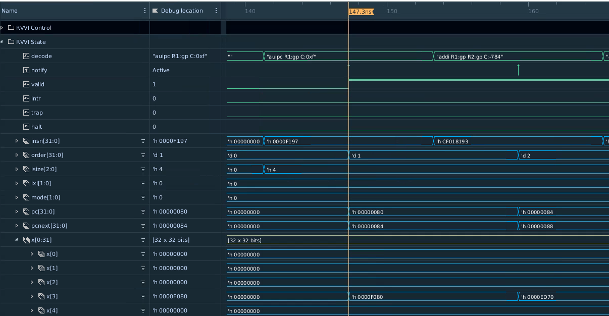
Illustration 5: RVVI State Instruction Example
RVVI Driver
The RVVI contains an active driver component which actually controls the reference model via the control virtual interface that was configured to the RVVI agent instance. The actual driver implementation will be discussed below.
The important features that the RVVI driver must accomplish are to:
Notify the reference model when normal program interruptions occur. These are usually external interrupts or external debug requests, but the implementation could be extended to any external event.
Step the reference model at the right time (i.e. after the RVFI completes an instruction)
The RVVI driver is implemented as a reactive slave. This differs from an active master where the user’s test would typically create and send sequence tiems to the driver. In this case, the RVVI driver is “driven” with sequence items that are created when the RVFI Monitor broadcasts a sequence itemm to its analysis port. The sequencer for RVVI implements an analysis_export that can receive RVFI instruction sequence items.
Thus when using the RVVI control driver the implmenter must connect the RVFI monitor analysis port to the sequencer’s analysis_export. Typically this higher-level connection would be handled in the processor’s UVM environment as below:
function void uvme_cv32e40x_env_c::connect_rvfi_rvvi();
   foreach (rvfi_agent.instr_mon_ap[i])
      rvfi_agent.instr_mon_ap[i].connect(rvvi_agent.sequencer.rvfi_instr_export);
endfunction : connect_rvfi_rvvi
Within the sequencer, the analsyis export simply pushes the RVFI sequence item to a queue in the sequencer:
function void uvma_rvvi_sqr_c::write_rvfi_instr(uvma_rvfi_instr_seq_item_c#(ILEN,XLEN) rvfi_instr);
   rvfi_instr_q.push_back(rvfi_instr);
endfunction : write_rvfi_instr
The RVVI agent itself will start a sequence on the sequencer at time 0 of the simulation. This sequence will run in perpetuity until the end of the simulation. The sequence will continuously poll the rvfi_instr_q and issue rvvi control sequence items to the driver (to step the reference model for instance) as RVFI sequence items are received.
In the actual driver it may be necessary to step the reference model multiple times per transaction received if an external asychronous event is signaled in the RVFI sequence item. See the Examples section for examples of this.
Core Scoreboard
With the RVFI and RVVI implemented, one can now create a scoreboard component that can verify processor operation as individual instructions are executed. The following diagram shows the full testbench environment for a RVFI/RVVI scoreboard.
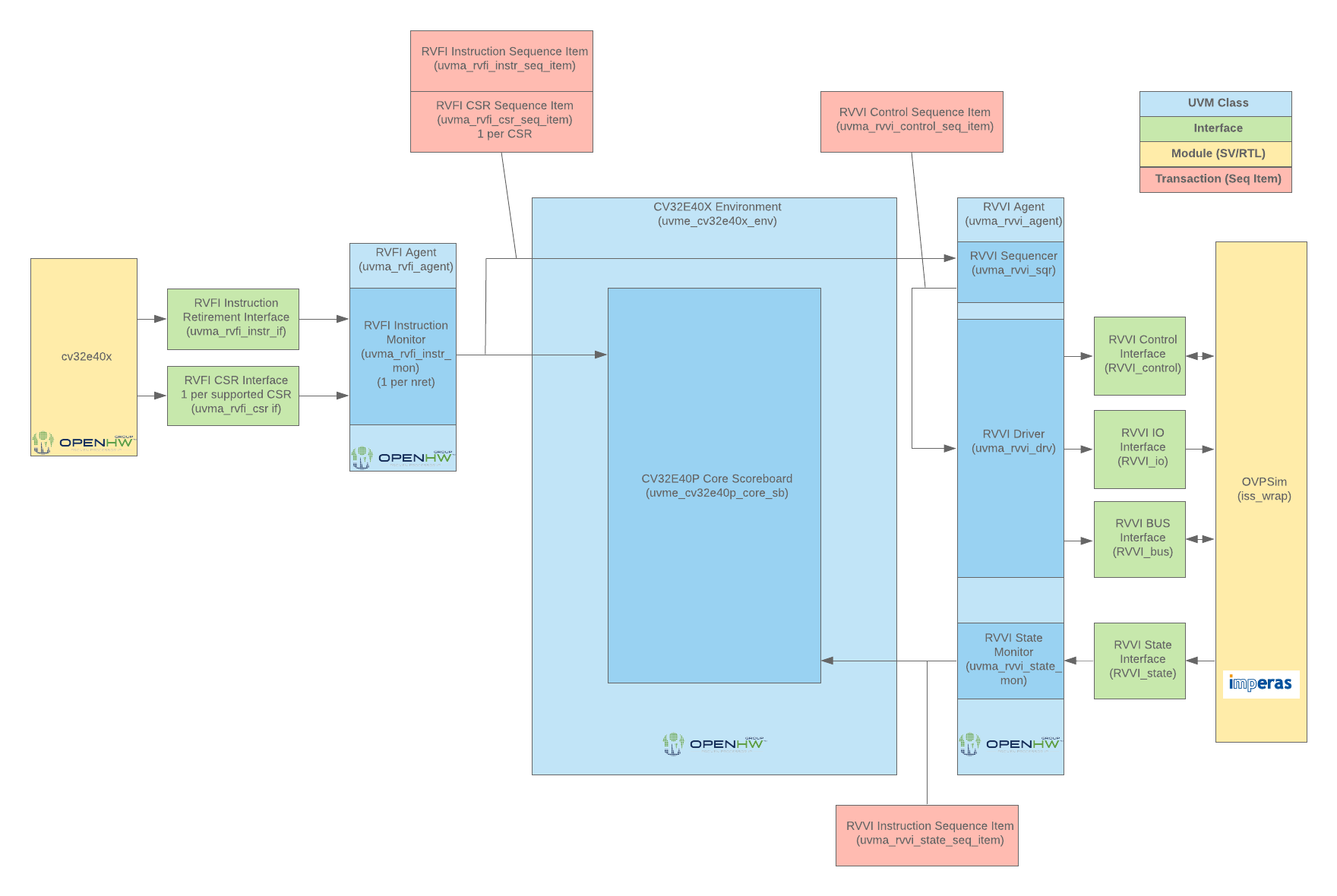
Illustration 6: Step and Compare 2.0 Scoreboard with RVFI and RVVI Agents
The Core Scoreboard is implemented and considered part of the core environment (e.g. cv32e40x_env_c). The scoreboard simply compares the sequence items received from the RVFI Monitor with the state received from the RVVI Monitor. In most embedded cores the instructions from each agent should arrive in order, however the scoreboard can work with multi-retirement cores (i.e. nret > 1) by using the unique order field in both RVFI and RVVI transactions to determine proper ordering.
The scoreboard is configured based on the following fields in the environment’s configuration object (e.g. cv32e40x_cfg_c).
Configuration class variable |
Default value |
Simulation make control |
Description |
|---|---|---|---|
scoreboarding_enabled |
1 |
USE_ISS=<0|1> |
Disables entire scoreboard and all checks |
scoreboarding_disable_csr_check_all |
0 |
Plusarg: +disable_csr_chk_all |
Disables checking of all CSR values in scoreboard |
scoreboarding_disable_csr_check |
Empty hash. Indexed by CSR name |
Plusarg: +disable_csr_chk=mip+mepc |
Disables checking of specific CSR values in scoreboard |
An individual test may configure the scoreboard within its test.yaml file. Each of the above could be configured via the following:
tests/programs/custom/hello-world/test.yaml

name: hello-world
uvm_test: uvmt_$(CV_CORE_LC)_firmware_test_c
description: >
   Simple hello-world sanity test
# This would disable the ISS (i.e. set scoreboarding_enabled = 0)
iss: 0
# This would disable all CSR checking
disable_csr_chk_all: 1
# This would disable CSR checks for mip, mepc, mcause
disable_csr_chk: >
   mip
   mepc
   mcause
For each instruction the following is checked:
PC of the retired instruction
GPR state including any updated GPR from the retired instruction
order field should be monotonically increasing (i.e. no skipped nor repeated order fields on either interface)
order field should match from RVFI to RVVI
CSR state as result of the instruction execution (i.e. CSR state at instruction retirement) should match
Examples
The following sections will give some examples to illustrate how instructions are checked in the scoreboard. Note that for all of these examples the RVVI wraps an Imperas RISCVOVPSim instance as the Reference Model. Other reference model implementations may slightly differ (when and if added in the future).
Instruction Check
The following waveform shows an instruction being successfully compared in the hello-world test.
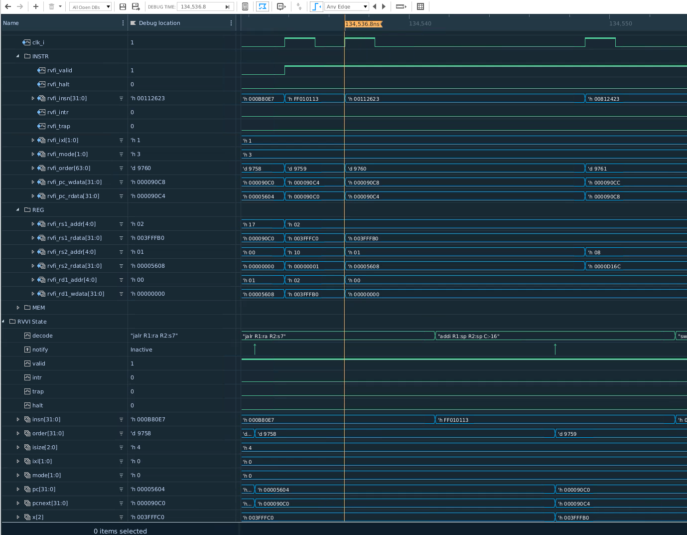
Illustration 7: Step and Compare 2.0 Scoreboard Instruction Check Example
The first event which start the instruction check cycle is the RVFI signalling that an instruction is complete by asserting rvfi_valid (see the cursor location in waveform). The RVFI Monitor will record all signals from the RVFI instruction, register, memory, and CSR interfaces into an RVFI sequence item as stated above.
When the RVVI Sequencer receives this transaction, the perpetual sequence that steps the Reference Model will send an approrpriate sequence item to the RVVI Driver. Note that this manifests on the waveforms by gating clocks to the DUT (i.e. RVFI). This is a consequence of how the Imperas RISCVOVPSim works and may not apply to other reference models. The RVVI Control Interface will step the Reference Model for one instruction.
On the RVVI state interface, the notify event asynchonrously signals that the Reference Model has retired an instruction. The RVVI State Monitor will sample all relevant signals from the RVVI State Interface into a sequence item for broadcast on its analysis port. Since the Reference Model and the state interface signal asynchronously as soon as the Reference Model completes, one should read waveform values to the right of the event. In the simulation these values are updated before the notify event such that the RVVI state monitor will pick up those new values. This is slightly non-intuitive versus reading signals at a clock edge (where you would typically read to the left of the positive edge for synchronous logic).
The Scoreboard upon receipt of the RVVI sequence item will then initiate a check (at the same simulation time as the notify event) versus the first RVFI sequence item in its queue. All fields will be checked, any errors reported and the sequence items then discarded.
CSR Check
Note
CSR checks occur simultaneously with RVFI and RVVI sequence items in an instruction check as described abovce. However they are presented in this separate section for clarification such that the specific CSR waveforms are highlighed.
The following waveform shows a CSR (mstatus) being check for an instruction in which it is being updated by the controller (from the interrupt_test test).
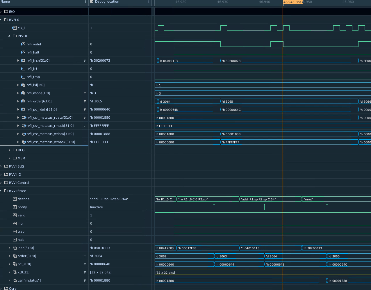
Illustration 8: Step and Compare 2.0 Scoreboard CSR Check Example
This example is a mret instruction retirement, which will update the mstatus register interrupt enables. The RVFI initially signals rvfi_valid and as part of the instruction monitoring, the CSR masks and data for mstatus are recorded. Note that since rvfi_csr_mstatus_wmask is set to 32’hffff_fffff, this designates that all bits of mstatus are updated by the instruction and thus rvfi_csr_mstatus_wdata will contain the value of the CSR at instruction retirement, which is 32’h0000_1888). Note that the previous instruction has a write mask of 0, and thus the CSR value of mstatus for the previous instruction on RVFI is 32’h0000_1080.
The RVVI state interface only shows the Reference Model’s expected value of mstatus at instruction retirement. This value is contained in the associative array csr under the csr name (csr[“mstatus”]). This value is also 32’h0000_1888 so the CSR will check properly at the notify event.
Interrupt Handler Check
On its own, the Reference Model cannot determine when interrupts to normal program flow occur, such as external interrupts or external debug requests. The RVFI monitors and reports those events, and thus the RVVI can be used to inform the Reference Model to interrupt normal program flow, maintaining processor state lock-step with the DUT.
The following example waveform shows entry into an interrupt handler due to external interrupt request assertion.
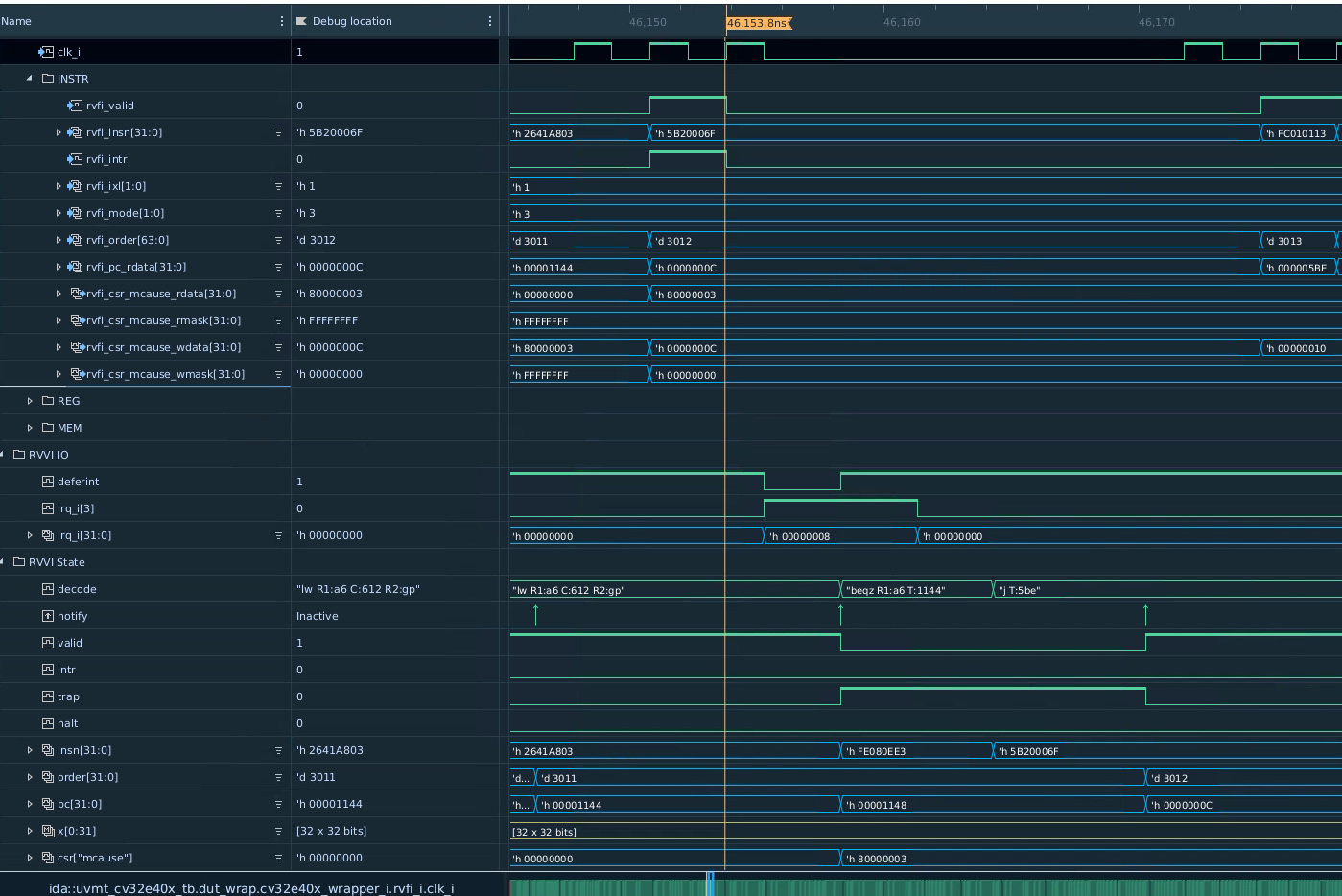
Illustration 9: Step and Compare 2.0 Scoreboard Interrupt Check Example
The example shows the very first instruction of an instruction handler. In this case the RVFI signals a valid instruction retirment with the rvfi_intr signal set. From the RVFI specification rvfi_intr signals that this instruction is the first instruction of any trap, which could be an exception (which the Reference Model can generally model without assistance) or an interrupt handler due to external signaling which requires assistance. To determine this, the RVVI control driver for the OVPSim will use the mcause value reported by the RVFI instruction. In this case the RVFI is reporting a value of 0x8000_0003. Since bit[31] is set, the trap is therefore an external interrupt.
Now that the RVVI OVPSim driver knows that an external interrupt of 0x3 is signaled from RVFI, it will assert deferint (active low) and irq_i) on the RVVI IO interface. Then it will step for an “instruction”. The Reference model then is signaled that an interrupt is to be entered. Note that due to the way OVPSim works, an extra step is required to actually step into the interrupt handler to retire the first instruction of the handler. Thus the RVFI and RVVI are re-synchronized. The RVVI monitor uses the *rvvi_valid signal in conjunction wit the rvvi.csr[“mcause”] value to determine that the notify event should be discarded for the deferint step.
Note
If an exception (e.g. illegal instruction) handler were entered and mcause[31] is deasserted, then that instruction should be checked against an RVFI instruction. (This may be better clarified via the valid signal on the RVVI state interface in the future).
Third Generation UVM Environment
At the time of this writing (2022-11-06), the third generation of the CV32E4* UVM verification environment is being rolled out. Watch this space for updates.