RISC-V Formal Interface (RVFI)
Note
A bindable RISC-V Formal Interface (RVFI) interface will be provided for CV32E40X. See [SYMBIOTIC-RVFI] for details on RVFI.
The module cv32e40x_rvfi can be used to create a log of the executed instructions.
It is a behavioral, non-synthesizable, module that can be bound to the cv32e40x_core.
RVFI serves the following purposes:
It can be used for formal verification.
It can be used to produce an instruction trace during simulation.
It can be used as a monitor to ease interfacing with an external scoreboard that itself can be interfaced to an Instruction Set Simulator (ISS) for verification reasons.
New Additions
Debug Signals
output [NRET * 3 - 1 : 0] rvfi_dbg
output [NRET     - 1 : 0] rvfi_dbg_mode
Debug entry is seen by RVFI as happening between instructions. This means that neither the last instruction before debug entry nor the first instruction of the debug handler will signal any direct side-effects. The first instruction of the handler will however show the resulting state caused by these side-effects (e.g. the CSR rmask/rdata signals will show the updated values, pc_rdata will be at the debug handler address, etc.).
For the first instruction after entering debug, the rvfi_dbg signal contains the debug cause (see table below). The signal is otherwise 0.
The rvfi_dbg_mode signal is high if the instruction was executed in debug mode and low otherwise.
Cause |
Value |
|---|---|
None |
0x0 |
Ebreak |
0x1 |
Trigger Match |
0x2 |
External Request |
0x3 |
Single Step |
0x4 |
Note
rvfi_dbg will not always match dcsr.CAUSE because an ebreak in debug mode will be reported via rvfi_dbg,
whereas dcsr.CAUSE will remain unchanged for that case.
NMI signals
output [1:0] rvfi_nmip
Whenever CV32E40X has a pending NMI, the rvfi_nmip will signal this. rvfi_nmip[0] will be 1 whenever an NMI is pending, while rvfi_nmip[1] will be 0 for loads and 1 for stores.
Memory interface signals
CV32E40X RVFI memory signals rvfi_mem_ are extended to support multiple memory operations per instruction and the following signals have been added:
output [ 1*NMEM-1:0] rvfi_mem_exokay,
output [ 1*NMEM-1:0] rvfi_mem_err,
output [ 3*NMEM-1:0] rvfi_mem_prot,
output [ 6*NMEM-1:0] rvfi_mem_atop,
output [ 2*NMEM-1:0] rvfi_mem_memtype,
output [ NMEM-1  :0] rvfi_mem_dbg
Integer register read/write
The integer register read/write signals have been extended to support multiple register file operations per instruction.
output [32*32-1:0] rvfi_gpr_rdata,
output [31:0]      rvfi_gpr_rmask,
output [32*32-1:0] rvfi_gpr_wdata,
output [31:0]      rvfi_gpr_wmask
Instruction fetch attributes
CV32E40X RVFI has been extended with the following signals for reporting attributes used when fetching an instruction.
output [2:0] rvfi_instr_prot,
output [1:0] rvfi_instr_memtype,
output       rvfi_instr_dbg
rvfi_trap and rvfi_intr
These two signals have been extended, see Compatibility.
Compatibility
This chapter specifies interpretations and compatibilities to the [SYMBIOTIC-RVFI].
Interface Qualification
All RVFI output signals are qualified with the rvfi_valid signal.
Any RVFI operation (retired or trapped instruction or trapped CLIC pointer) will set rvfi_valid high and increment the rvfi_order field.
When rvfi_valid is low, all other RVFI outputs can be driven to arbitrary values.
Trap Signal
The trap signal indicates that a synchronous trap has ocurred and side-effects can be expected.
output rvfi_trap_t[NRET - 1 : 0] rvfi_trap
Where the rvfi_trap_t struct contains the following fields:
Field |
Type |
Bits |
|---|---|---|
trap |
logic |
[0] |
exception |
logic |
[1] |
debug |
logic |
[2] |
exception_cause |
logic [5:0] |
[8:3] |
debug_cause |
logic [2:0] |
[11:9] |
cause_type |
logic [1:0] |
[13:12] |
clicptr |
logic |
[14] |
rvfi_trap consists of 15 bits.
rvfi_trap.trap is asserted if an instruction or CLIC pointer causes an exception or debug entry.
rvfi_trap.exception is set for synchronous traps that do not cause debug entry. rvfi_trap.debug is set for synchronous traps that do cause debug mode entry.
rvfi_trap.exception_cause provide information about non-debug traps, while rvfi_trap.debug_cause provide information about traps causing entry to debug mode.
rvfi_trap.cause_type differentiates between fault causes that map to the same exception code in rvfi_trap.exception_cause and rvfi_trap.debug_cause.
rvfi_trap.clicptr is set for CLIC pointers. CLIC pointers are only reported on RVFI when they get an exception during fetch.
When an exception is caused by a single stepped instruction, both rvfi_trap.exception and rvfi_trap.debug will be set.
When rvfi_trap signals a trap, CSR side effects and a jump to a trap/debug handler in the next cycle can be expected.
The different trap scenarios, their expected side-effects and trap signalling are listed in the table below:
Scenario |
Trap Type |
rvfi_trap |
CSRs updated |
Description |
||||||
|---|---|---|---|---|---|---|---|---|---|---|
trap |
exception |
debug |
exception_cause |
debug_cause |
cause_type |
clicptr |
||||
Instruction Access Fault |
Exception |
1 |
1 |
X |
0x01 |
X |
0x0 |
0 / 1 |
|
PMA detects instruction execution from non-executable memory. |
Illegal Instruction |
Exception |
1 |
1 |
X |
0x02 |
X |
0x0 |
0 |
|
Illegal instruction decode. |
Breakpoint |
Exception |
1 |
1 |
X |
0x03 |
X |
0x0 |
0 |
|
EBREAK executed with |
Load Address Misaligned |
Exception |
1 |
1 |
X |
0x04 |
X |
0x0 |
0 |
|
Non-naturally aligned Load-Reserved address. |
Load Access Fault |
Exception |
1 |
1 |
X |
0x05 |
X |
0x0 |
0 |
|
Non-naturally aligned load access attempt to an I/O region. |
0x1 |
0 |
|
Load-Reserved attempt to region without atomic support. |
|||||||
Store/AMO Address Misaligned |
Exception |
1 |
1 |
X |
0x06 |
X |
0x0 |
0 |
|
Non-naturally aligned Store-Conditional / AMO address. |
Store/AMO Access Fault |
Exception |
1 |
1 |
X |
0x07 |
X |
0x0 |
0 |
|
Non-naturally aligned store access attempt to an I/O region. |
0x1 |
0 |
|
SC or AMO attempt to region without atomic support. |
|||||||
Environment Call |
Exception |
1 |
1 |
X |
0x0B |
X |
0x0 |
0 |
|
ECALL executed from Machine mode. |
Instruction Bus Fault |
Exception |
1 |
1 |
X |
0x18 |
X |
0x0 |
0 / 1 |
|
OBI bus error on instruction fetch. |
Breakpoint to debug |
Debug |
1 |
0 |
1 |
X |
0x1 |
0x0 |
0 |
|
EBREAK from non-debug mode executed with |
Breakpoint in debug |
Debug |
1 |
0 |
1 |
X |
0x1 |
0x0 |
0 |
No CSRs updated |
EBREAK in debug mode jumps to debug handler. |
Debug Trigger Match |
Debug |
1 |
0 |
1 |
X |
0x2 |
0x0 |
0 |
|
Debug trigger address match with |
Single step |
Debug |
1 |
X |
1 |
X |
0x4 |
X |
0 |
|
Single step. |
Interrupts
Interrupts are seen by RVFI as happening between instructions. This means that neither the last instruction before the interrupt nor the first instruction of the interrupt handler will signal any direct side-effects. The first instruction of the handler will however show the resulting state caused by these side-effects (e.g. the CSR rmask/rdata signals will show the updated values, pc_rdata will be at the interrupt handler address etc.).
output rvfi_intr_t[NRET - 1 : 0] rvfi_intr
Where the rvfi_intr_t struct contains the following fields:
Field |
Type |
Bits |
|---|---|---|
intr |
logic |
[0] |
exception |
logic |
[1] |
interrupt |
logic |
[2] |
cause |
logic [10:0] |
[13:3] |
rvfi_intr consists of 14 bits.
rvfi_intr.intr is set for the first instruction of the trap handler when encountering an exception or interrupt.
rvfi_intr.exception indicates it was caused by synchronous trap and
rvfi_intr.interrupt indicates it was caused by an interrupt.
rvfi_intr.cause signals the cause for entering the trap handler.
Scenario |
rvfi_intr |
rvfi_dbg[2:0] |
mcause[31] |
dcsr[8:6] (cause) |
|||
|---|---|---|---|---|---|---|---|
intr |
exception |
interrupt |
cause |
||||
Synchronous trap |
1 |
1 |
0 |
Sync trap cause |
0x0 |
0 |
|
Interrupt (includes NMIs from bus errors) |
1 |
0 |
1 |
Interrupt cause |
0x0 |
1 |
|
Debug entry due to EBREAK (from non-debug mode) |
0 |
0 |
0 |
0x0 |
0x1 |
0x1 |
|
Debug entry due to EBREAK (from debug mode) |
0 |
0 |
0 |
0x0 |
0x1 |
||
Debug entry due to trigger match |
0 |
0 |
0 |
0x0 |
0x2 |
0x2 |
|
Debug entry due to external debug request |
X |
X |
X |
X |
0x3 or 0x5 |
X |
0x3 or 0x5 |
Debug handler entry due to single step |
X |
X |
X |
X |
0x4 |
X |
0x4 |
Note
In above table the - symbol indicates an unchanged value. The X symbol indicates that multiple values are possible.
Note
rvfi_intr is not set for debug traps unless a debug entry happens during the first instruction of a trap handler (see rvfi_intr == X in the table above).
In this case CSR side-effects (to mepc and mcause) can be expected as well.
Program Counter
The pc_wdata signal shows the predicted next program counter. This prediction ignores asynchronous traps (asynchronous debug requests and interrupts) and single step debug requests that may have happened at the same time as the instruction.
Memory Access
For CV32E40X, the rvfi_mem interface has been expanded to support multiple memory operations per instruction. The new format of the rvfi_mem signals can be seen in the code block below.
output [NRET * NMEM * XLEN   - 1 : 0] rvfi_mem_addr
output [NRET * NMEM * XLEN/8 - 1 : 0] rvfi_mem_rmask
output [NRET * NMEM * XLEN/8 - 1 : 0] rvfi_mem_wmask
output [NRET * NMEM * XLEN   - 1 : 0] rvfi_mem_rdata
output [NRET * NMEM * XLEN   - 1 : 0] rvfi_mem_wdata
output [NRET * NMEM * 3      - 1 : 0] rvfi_mem_prot
output [NRET * NMEM * 6      - 1 : 0] rvfi_mem_atop
output [NRET * NMEM * 1      - 1 : 0] rvfi_mem_err
output [NRET * NMEM * 1      - 1 : 0] rvfi_mem_exokay
output [NRET * NMEM * 2      - 1 : 0] rvfi_mem_memtype
output [       NMEM          - 1 : 0] rvfi_mem_dbg
Instructions will populate the rvfi_mem outputs with incrementing NMEM, starting at NMEM=1.
Instructions with a single memory operation (e.g. all RV32I instructions), including split misaligned transfers, will only use NMEM = 1.
Instructions with multiple memory operations (e.g. the push and pop instructions from Zcmp) use NMEM > 1 in case multiple memory operations actually occur.
rvfi_mem_prot indicates the value of OBI prot used for the memory access or accesses. Note that this will be undefined upon access faults.
rvfi_mem_memtype indicates the memory type attributes associated with each memory operation (i.e cacheable or bufferable). For misaligned transactions that are
split in two memory operations rvfi_mem_memtype will only report the type attribute for the first memory operation.
rvfi_mem_atop indicates the type of atomic transaction as specified in [OPENHW-OBI].
rvfi_mem_exokay indicates the status of data_exokay_i for loads, non-bufferable stores and atomic instructions (and signals 0 otherwise). For split transactions, rvfi_mem_exokay will only
be 1 if both transactions receive data_exokay_i == 1.
rvfi_mem_err indicates if a load, non-bufferable store or atomic instruction got a bus error (and signals 0 otherwise). Table 29 shows how
different memory transactions report rvfi_mem_err.
Instruction type |
Split |
Bufferable (1) |
Bufferable (2) |
rvfi_mem_err |
|---|---|---|---|---|
Load |
No |
N/A |
N/A |
data_err_i |
Load |
Yes |
N/A |
N/A |
data_err_i(1) OR data_err_i(2) |
Store |
No |
No |
N/A |
data_err_i |
Store |
No |
Yes |
N/A |
0 |
Store |
Yes |
No |
No |
data_err_i(1) OR data_err_i(2) |
Store |
Yes |
Yes |
Yes |
0 |
Store |
Yes |
Yes |
No |
data_err_i(2) |
Store |
Yes |
No |
Yes |
data_err_i(1) |
rvfi_mem_rdata will report the read data for load instructions. In case of split misaligned transactions this read data is the combination of the two transfers.
For cores as CV32E40X that support misaligned access rvfi_mem_addr will not always be 4 byte aligned. For misaligned accesses the start address of the transfer is reported (i.e. the start address of the first sub-transfer).
Note
rvfi_mem_exokay and rvfi_mem_err will not be reported for bufferable writes (tied to zero). Bufferable writes may get their responses after the instructions have retired.
Note
RVFI for CV32E40X currently has limited support for AMO instructions.
AMO instructions will only set rvfi_mem_wmask and not rvfi_mem_rmask.
The value written to memory by AMO (read-modify-write) instructions is modified outside of CV32E40X before being written to memory. This results in the value of rvfi_mem_wdata to not reflect the value written to memory.
See Atomic Memory Operations for details on AMO instructions.
CSR Signals
To reduce the number of signals in the RVFI interface, a vectorized CSR interface has been introduced for register ranges.
output [<NUM_CSRNAME>-1:0] [NRET * XLEN - 1 : 0] rvfi_csr_<csrname>_rmask
output [<NUM_CSRNAME>-1:0] [NRET * XLEN - 1 : 0] rvfi_csr_<csrname>_wmask
output [<NUM_CSRNAME>-1:0] [NRET * XLEN - 1 : 0] rvfi_csr_<csrname>_rdata
output [<NUM_CSRNAME>-1:0] [NRET * XLEN - 1 : 0] rvfi_csr_<csrname>_wdata
Example:
output [31:0] [31:0] rvfi_csr_name_rmask
output [31:0] [31:0] rvfi_csr_name_wmask
output [31:0] [31:0] rvfi_csr_name_rdata
output [31:0] [31:0] rvfi_csr_name_wdata
Instead of:
output [31:0] rvfi_csr_name0_rmask
output [31:0] rvfi_csr_name0_wmask
output [31:0] rvfi_csr_name0_rdata
output [31:0] rvfi_csr_name0_wdata
. . .
output [31:0] rvfi_csr_name31_rmask
output [31:0] rvfi_csr_name31_wmask
output [31:0] rvfi_csr_name31_rdata
output [31:0] rvfi_csr_name31_wdata
CSR mnxti
CSR accesses to the mnxti CSR do a read-modify-write on the mstatus CSR, and return a pointer address if there is a pending non-SHV CLIC interrupt.
If there is a pending non-SHV CLIC interrupt, it also updates mintstatus and mcause.
To reflect this behavior, the rvfi_csr_mnxti* outputs for mnxti have a different semantic than other CSRs.
The rvfi_csr_mnxti* is reported as follows on RVFI:
The
rmaskwill always be all ones as for other CSRs.The
wmaskwill be all ones whenever the CSR instruction actually writes tomstatus.The
wdatawill be the data written tomstatus.The
rdatawill report a pointer address if an interrupt is pending, or 0 if no interrupt is pending.
Note that the rvfi_csr_mstatus* will also reflect the access to mstatus due to an mnxti access.
In case the access to mnxti returns a valid pointer address, the rvfi_csr_mintstatus* and rvfi_csr_mcause* will also have values showing the side effects of accessing mnxti.
GPR signals
For CV32E40X, RVFI has been expanded to allow reporting multiple register file operations per instruction (more than two reads and one write). The interface is defined as follows:
output [NRET * 32 * XLEN - 1 : 0] rvfi_gpr_rdata
output [NRET * 32 -1 : 0]         rvfi_gpr_rmask
output [NRET * 32 * XLEN - 1 : 0] rvfi_gpr_wdata
output [NRET * 32 -1 : 0]         rvfi_gpr_wmask
The outputs rvfi_gpr_rdata and rvfi_gpr_wdata reflect the entire register file, with each XLEN field of the vector representing one GPR, with [x0] starting at index [XLEN - 1 : 0], [x1] at index [2*XLEN-1 -: XLEN] and so on.
Each bit in the outputs rvfi_gpr_rmask and rvfi_gpr_wmask indicates if a GPR has been read or written during an instruction. The index of the bit indicates the address of the GPR accessed. Entries in rvfi_gpr_rdata
and rvfi_gpr_wdata are only considered valid if the corresponding bit in the rvfi_gpr_rmask or rvfi_gpr_wmask is set.
Machine Counter/Timers
In contrast to [SYMBIOTIC-RVFI], the mcycle[h] and minstret[h] registers are not modelled as happening “between instructions” but rather as a side-effect of the instruction.
This means that an instruction that causes an increment (or decrement) of these counters will set the rvfi_csr_mcycle_wmask, and that rvfi_csr_mcycle_rdata is not necessarily equal to rvfi_csr_mcycle_wdata.
Halt Signal
The rvfi_halt signal is meant for liveness properties of cores that can halt execution. It is only needed for cores that can lock up. Tied to 0 for RISC-V compliant cores.
Mode Signal
The rvfi_mode signal shows the current privilege mode as opposed to the effective privilege mode of the instruction. I.e. for load and store instructions the reported privilege level will therefore not depend on mstatus.mpp and mstatus.mprv.
OBI prot Signal
rvfi_instr_prot indicates the value of OBI prot used for fetching the retired instruction. Note that this will be undefined upon access faults.
Simulation trace
The module cv32e40x_rvfi_sim_trace can be bound to cv32e40x_rvfi to enable tracing capabilities.
cv32e40x_rvfi_sim_trace supports trace output to log file and trace annotation in waveforms.
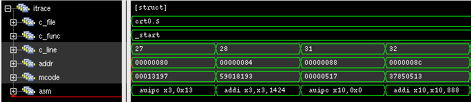
Trace annotation in waveforms is enabled by providing the path to an .itb file through the simulation plusarg itb_file. The name of the plusarg can be overridden through the cv32e40x_rvfi_sim_trace parameter ITB_PLUSARG.
The struct itrace in cv32e40x_rvfi_sim_trace will contain information about the most recently retired instruction.
Trace output to log is enabled by providing log file path through the simulation plusarg log_file. The name of the plusarg can be overridden through the cv32e40x_rvfi_sim_trace parameter LOGFILE_PATH_PLUSARG.
Trace output format
The trace log file format is as described below.
pc: The program counter
rs1(data) Register read port 1 source register and read data
rs2(data) Register read port 2 source register and read data
rd(data) Register write port 1 destination register and write data
memaddr Memory address for instructions accessing memory
rmask Bitmask specifying which bytes in
rdatacontain valid read datardata The data read from memory address specified in
memaddrwmask Bitmask specifying which bytes in
wdatacontain valid write datawdata The data written to memory address specified in
memaddrAssembly Assembly code. This column is only populated if an itb file is provided
pc         | rs1 (   data   ) | rs2 (   data   ) | rd  (   data   ) | memaddr    | rmask  | rdata      | wmask  | wdata      ||  Assembly
0x00000080 | x0  (0x00000000) | x0  (0x00000000) | x3  (0x00013080) | 0x00013080 | 0x0000 | 0x00000000 | 0x0000 | 0x00000000 ||   auipc x3,0x13
0x00000084 | x3  (0x00013080) | x0  (0x00000000) | x3  (0x00013610) | 0x00013610 | 0x0000 | 0x00000000 | 0x0000 | 0x00000000 ||   addi x3,x3,1424
0x00000088 | x0  (0x00000000) | x0  (0x00000000) | x10 (0x00000088) | 0x00000088 | 0x0000 | 0x00000000 | 0x0000 | 0x00000000 ||   auipc x10,0x0
0x0000008c | x10 (0x00000088) | x0  (0x00000000) | x10 (0x00000400) | 0x00000400 | 0x0000 | 0x00000000 | 0x0000 | 0x00000000 ||   addi x10,x10,888
The waveform annotation for the same trace is depicted below: